Typical procedure
A small section of the optical fiber’s buffer layer is stripped to expose the fiber. The fiber end is cleaved to produce a clean and perpendicular cut. The fiber is then fusion spliced to the second fiber end and the splice reinforced with a protection sleeve. The method of fusion splice provides much lower insertion loss compared to fiber connectorization process. This service is available for Singlemode, Polarization Maintaining and Multimode fibers with diameters under 600µm (larger diameters upon customer’s request).
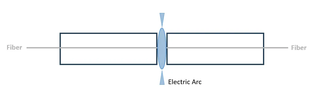
Fusion Splice
Fusion splices are more permanent solution for continuous fiber application. They have the best return loss performance of all the mating and mechanic splicing technique, due to the action of creating one continuous fiber optic train. If fibers with identical core and cladding dimensions are used, the interface is nearly non-existing.
As the fusion splice itself can be strong, the region around the splicing area can be weakened due to the heating process during splicing. It is recommended that strain relief and/or strength members be used.
The fusion splicer performs optical fiber fusion splicing in two steps:
- Precisely align the two fibers
- Generate a small electric arc to melt the fibers and fused them together. This produces a transparent, non-reflective and continuous connection between the fibers enabling very low loss light transmission.
The advantages of this approach are that the linking method is fast and simple and has a longer life than the mechanical splicing. There are very little insertion loss and lower splicing loss at 0.1dB typical.
The common application for splicing is joining cables in long outside plant cable runs. This is where a length of a run requires more than one cable. Splicing is generally used to terminate singlemode fibers (by splicing pre-terminated pigtails onto each fiber) but there are many other uses.
Splicing Quality Control
The first control of the splice is a visual inspection on the screen and the losses estimation measured by the splicer itself.
Optical time-domain reflectometry (OTDR) is used for checking fiber cables including splices. At least serious faults are easily recognized and located with that technique.