Quality endfaces can be obtained by polishing or by cleaving. After stripping a cable, polishing is employed in connector terminations when the fiber is secured in a ferrule by epoxy. There are two types of fiber connectors: physical contact or expanded beam. See below our different services of connectorization:
Fiber Stripping
The outer sheath of fiber cables can be removed using electrical cable stripping tools, and scissors or a razor blade can trim the Kevlar strength member. However, the fiber coating must be very carefully removed to avoid damaging the fiber — surface flaws and scratches are the cause of most fiber failures. The coating can be removed using our fiber strippers.
Fiber Cleaving
Fiber Cleaving is the fastest way to achieve a mirror-flat fiber end — it takes only seconds. The basic principle involves placing the fiber under tension, scribing with a diamond or carbide blade perpendicular to the axis, and then pulling the fiber apart to produce a clean break.
Fiber Termination – Physical Contact Connectors
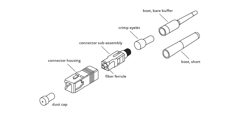
Endface surface quality is one of the most important factors affecting fiber connector and splice losses. A physical connector terminates the optical fiber inside a ceramic ferrule, using epoxy to hold the fiber in place. The principle of physical contact connectors involves the direct contact of polished fibers within two ceramic ferrules. The ferrules are aligned using a ceramic alignment sleeve. There are springs behind the ferrule to ensure that the two ferrules are in constant contact even in high vibration and shock environments. This also allows easy handling of the fiber and protects it from damage.
The major performance characteristics of connectors are:
- Insertion loss: It is the amount of power lost in transmission due to the connection. They are between 0.25 dB – 0.5 dB. It is a function of the alignment accuracy and the polish quality.
- Return loss quantifies how much power is reflected backwards from the connection:
- Repeatability
Their insertion loss is generally low: approximately 0.3dB. There are many types of fiber optic connectors used in various applications. The most popular single fiber connectors are: FC, LC, SC, ST.
Once the optical fiber is terminated with a particular connector, the connector endface preparation will determine what the connector return loss, also known as back reflection, will be.
There are three major types of polishing of these connectors:
Type of connector | Design | Key | Return Loss | Compatible fibers |
PC | The tip is slightly curved to ensure only the fiber cores make connection during mating and not the ferrules themselves by eliminating the fiber-to-air interface. | 2.00mm | 25-40 dB |
o key is aligned to slow axis of FC/APC |
UPC | Higher quality polish with rounder edges than PC to ensure better core mating. | – | 45-50 dB |
key is aligned to slow axis |
APC | 8 degree of angle present in the ferrule tip. | Narrow or Wide keyed = 2.02 or 2.14mm | 55-70 dB |
o key is aligned to slow axis |
Two Process:
Traditional Epoxy and Polish Fiber Connectors
Epoxy or Polish Fiber Connectors are very traditional and widely used connectors. You may find that most factory-made connectors are epoxy or polish style owing that the epoxy or polish type is relatively reliable with low cost and low loss through a multi-factor consideration. The fiber is glued into the connector with epoxy and the end polished with a special polishing film. Such traditional epoxy and polish fiber connectors are needed for the applications where many connectors will be used.
Quick Termination Fiber Optic Connectors
For quick termination fiber optic connectors, there has been a fiber stub bonded into the ferrule, where the end face of the ferrule is polished to a PC/UPC/APC finish. The other end of the fiber is cleaved and resides inside the connector body. It is more costly than the epoxy and polish fiber connectors.
Advantages are that the connectors can be mated and unmated at any time. The advantages of this approach are that the connection is robust, the connector can be chosen according to the application, and the connector can be connected and disconnected hundreds or even thousands of time without damaging the connectors. These physical contact connectors perform well against particle contaminates and are usually less sensitive to liquid contaminates.
The disadvantages of this approach are that the connectorization takes longer than fusion splicing, requires special tools, and the insertion loss can be higher when compared with fusion splicing.
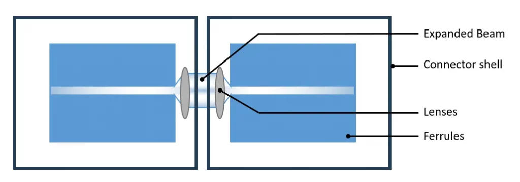
Fiber Termination - Expanded beam
This technology consists of placing a lens at the exit of each fiber to widen and collimate the light. In this configuration, there is an air gap between the two optical fibers/lens assemblies. The mechanical interface between the connectors must be precise. Expanded beam connectors are less susceptible to particle contaminates such as dirt and dust but they perform poorly with liquids or film on the lenses. They can also be very difficult to terminate in the field. The loss generated by an expanded beam connection is more than that of a physical contact connector due to the lenses, mechanical alignment and sometimes protective windows (approximately 0.8 to 2.5dB typical).
Connector Quality Control
We control the aspect of each connector and monitor the loss with a visual fault locator when terminating an assembly. If there is something wrong with the termination process, both the connector and the two splices will be lost.